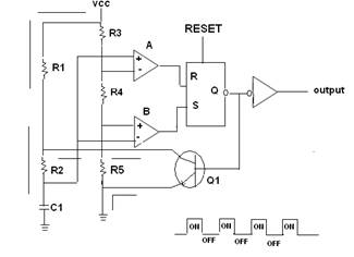
555 Timer Internal Schematic : 555 Timer Circuits. This is the basic mode of operation of the ic 555. An open collector is a common type of output found on many integrated circuits (ic), which behaves like a switch that is either connected to ground or disconnected.instead of outputting a signal of a specific voltage or current, the output signal is applied to the base of an internal npn transistor whose collector is externalized (open) on a pin of the ic. Jun 16, 2015 · the following figure is the schematic of ic 555 as a monostable multivibrator. This tutorial provides sample circuits to set up a 555 timer in monostable, astable, and bistable modes as well as an in depth discussion of how the 555 timer works and how to choose components to use with it. Between the positive supply voltage v cc and the ground gnd is a voltage divider consisting of three identical resistors , which create two reference voltages at 1 ⁄ 3 v cc and.
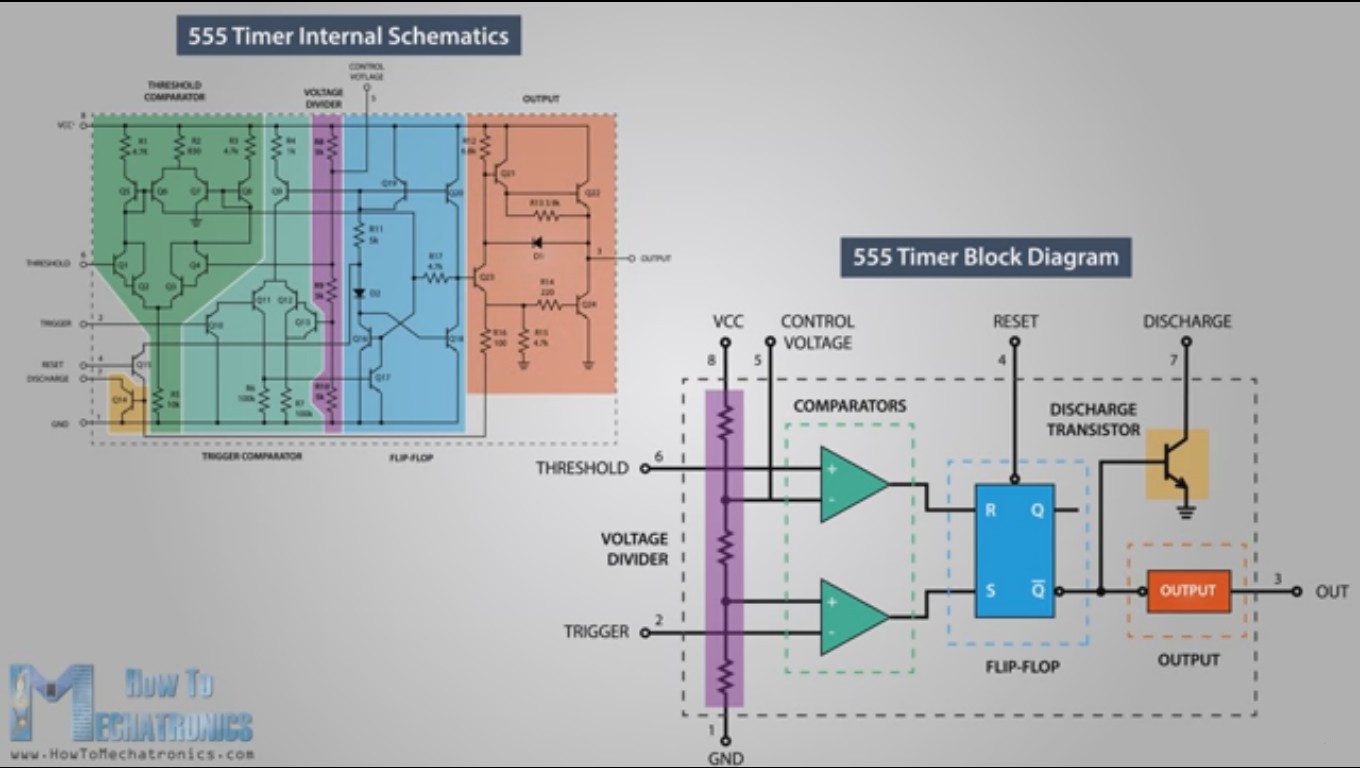
The internal block diagram and schematic of the 555 timer are highlighted with the same color across all three drawings to clarify how the chip is implemented: Learn by doing is the best. It was commercialized in 1972 by signetics. As the name specifies, a monostable multivibrator has only one stable state. In 2017, it was said over a billion 555 timers are pr.
555 Timer Ic As A Stable Multivibrator from www.daenotes.com 555 internal circuit consists of three series 5k resistors connected between the vcc and gnd. This circuit is also called a delay. It requires only two extra components to make it work as a monostable multivibrator: Ic 7555 is the cmos version of the 555 ic with same pin configuration and function. Schematic of 555 or 1/2 556 dual t imer. The 555 timer is a chip that can be us… Internal diagram of 555 timer ic. It was commercialized in 1972 by signetics.
There will be minor internal circuitry differences between 555 timer ic's from the various manufacturers but they all should be useable for the circuits on this page.
There will be minor internal circuitry differences between 555 timer ic's from the various manufacturers but they all should be useable for the circuits on this page. Internal resistor divider network, r7, r8,. This is the basic mode of operation of the ic 555. Ic 7555 is the cmos version of the 555 ic with same pin configuration and function. Derivatives provide two (556) or four (558) timing circuits in one package. This tutorial provides sample circuits to set up a 555 timer in monostable, astable, and bistable modes as well as an in depth discussion of how the 555 timer works and how to choose components to use with it. You may already know that se/ne 555 is a timer ic introduced by signetics corporation in 1970's. Apr 15, 2020 · people know it as the 555 timer ic. In 2017, it was said over a billion 555 timers are pr. In this article, we cover the following information about 555 timer ic. Jun 16, 2015 · the following figure is the schematic of ic 555 as a monostable multivibrator. It was commercialized in 1972 by signetics. Internal diagram of 555 timer ic.
A resistor and a capacitor. Derivatives provide two (556) or four (558) timing circuits in one package. Dec 07, 2018 · the ic 556 and ic 558 are 14 pins dual timer and 16 pin quad timer versions of the ic 555 respectively. The rc timing circuit incorporates r 1 , r 2 and c. The 555 timer is a chip that can be us…
Learning The 555 From The Inside Hackaday from hackaday.com Simple ne555 ic tester circuit diagram. A resistor and a capacitor. In 2017, it was said over a billion 555 timers are pr. Internal resistor divider network, r7, r8,. As the name specifies, a monostable multivibrator has only one stable state. Jun 16, 2015 · the following figure is the schematic of ic 555 as a monostable multivibrator. You may already know that se/ne 555 is a timer ic introduced by signetics corporation in 1970's. The internal block diagram and schematic of the 555 timer are highlighted with the same color across all three drawings to clarify how the chip is implemented:
There will be minor internal circuitry differences between 555 timer ic's from the various manufacturers but they all should be useable for the circuits on this page.
The 555 timer consists of two voltage comparators, a bistable. We can use the 555 as a timer for up to 10 minutes. This is the basic mode of operation of the ic 555. In this article, we cover the following information about 555 timer ic. Simple ne555 ic tester circuit diagram. Apr 15, 2020 · people know it as the 555 timer ic. A resistor and a capacitor. Between the positive supply voltage v cc and the ground gnd is a voltage divider consisting of three identical resistors , which create two reference voltages at 1 ⁄ 3 v cc and. The rc timing circuit incorporates r 1 , r 2 and c. You may already know that se/ne 555 is a timer ic introduced by signetics corporation in 1970's. As the name specifies, a monostable multivibrator has only one stable state. The 555 timer ic is an integrated circuit (chip) used in a variety of timer, delay, pulse generation, and oscillator applications. Schematic of 555 or 1/2 556 dual t imer.
Simple ne555 ic tester circuit diagram. Between the positive supply voltage v cc and the ground gnd is a voltage divider consisting of three identical resistors , which create two reference voltages at 1 ⁄ 3 v cc and. A resistor and a capacitor. Schematic of 555 or 1/2 556 dual t imer. An open collector is a common type of output found on many integrated circuits (ic), which behaves like a switch that is either connected to ground or disconnected.instead of outputting a signal of a specific voltage or current, the output signal is applied to the base of an internal npn transistor whose collector is externalized (open) on a pin of the ic.
555 Timer Teardown Inside The World S Most Popular Ic from static.righto.com 555 internal circuit consists of three series 5k resistors connected between the vcc and gnd. This circuit is also called a delay. Apr 15, 2020 · people know it as the 555 timer ic. An open collector is a common type of output found on many integrated circuits (ic), which behaves like a switch that is either connected to ground or disconnected.instead of outputting a signal of a specific voltage or current, the output signal is applied to the base of an internal npn transistor whose collector is externalized (open) on a pin of the ic. If you would like to use any of these ideas, do some testing before using the lm555 or lm556 timer in an actual circuit. Ic 7555 is the cmos version of the 555 ic with same pin configuration and function. This article covers every basic aspect of 555 timer ic. It was commercialized in 1972 by signetics.
You may already know that se/ne 555 is a timer ic introduced by signetics corporation in 1970's.
The internal block diagram and schematic of the 555 timer are highlighted with the same color across all three drawings to clarify how the chip is implemented: An open collector is a common type of output found on many integrated circuits (ic), which behaves like a switch that is either connected to ground or disconnected.instead of outputting a signal of a specific voltage or current, the output signal is applied to the base of an internal npn transistor whose collector is externalized (open) on a pin of the ic. Ic 7555 is the cmos version of the 555 ic with same pin configuration and function. The 555 timer consists of two voltage comparators, a bistable. This article covers every basic aspect of 555 timer ic. Schematic of 555 or 1/2 556 dual t imer. The 555 timer ic is an integrated circuit (chip) used in a variety of timer, delay, pulse generation, and oscillator applications. Internal diagram of 555 timer ic. The 555 timer is a chip that can be us… Learn by doing is the best. Simple ne555 ic tester circuit diagram. In this article, we cover the following information about 555 timer ic. This is the basic mode of operation of the ic 555.
We can use the 555 as a timer for up to 10 minutes 555 timer schematic. A resistor and a capacitor.
Share :
Post a Comment
for "555 Timer Internal Schematic : 555 Timer Circuits"


Post a Comment for "555 Timer Internal Schematic : 555 Timer Circuits"